This lab was designed to practice surveying skills on large areas on land without the use of GPS technology or survey stations. Often GPS and other advanced technology can fail or not be available and it is important to know how to survey even with the most basic techniques. This lab uses the concept of distance and azimuth to complete a survey of the location of trees in an area of Putnam Park.
Study Area
The survey was conducted in Putnam Park on the University of Wisconsin- Eau Claire campus along Putnam Drive. Putnam Park is a heavily forested area that curves through part of the Eau Claire campus. Putnam Park is owned by the university and was named a designated State Natural Area in 1976.

Figure 1. The area of Putnam Park that was used for the tree survey on the University of Wisconsin- Eau Claire campus.
Methods
There are two different types of geographic data, explicit and implicit.
Explicit geographic data is data collected within centimeters of accuracy. This data is collected using unmanned aerial vehicles (UAVS) and the data is typically only of great need by professional surveyors.
Implicit geographic data is collected for its relative use. This data is not concerned with exact measurements and exact locations, but rather is generated for the overall layout of a geographic area.
In this lab implicit geographic data was created by using two measurements, distance and azimuth, from a geographic location. Three different surveying methods were used each at a different location in Putnam Park to determine the location of the trees and diameter of the trees in the area. For each tree recorded at each of the three locations four things were recorded. The geographic coordinates of the origin (the origin was the same for all trees collected at each of the three locations), the distance (meters), the azimuth (degrees), and the diameter of the tree being measured (centimeters). With the combination of these four measurements a survey of the relative location of some trees and the diameter of these trees can be generated.
This lab took it back to the basics using only hand held devices and no advanced GPS systems. At each of the three locations where a different survey method was used first the specific coordinates of a specified location were recorded. This location served as the origin from where the distance and azimuth were measured from for the trees in the area. The origin coordinates used at each of the three locations was recorded and converted to decimal degrees. Also at every location a compass was used to record the azimuth of each tree being recorded from the origin. The last piece of equipment used at each location was a DBH tape, a tape measure especially made to measure the diameter at breast height of a tree. All three of these devices can be seen in figures 2 and 3. Figure 4 shows a diagrams of how to measure DBH. The measuring tape was wrapped around the tree trunk at chest height of the surveyor to obtain the measurement of the diameter of the tree at breast height.


Figure 2. Compass used at each Figure 3. GPS unit used to get origin
location to measure the azimuth of coordinated and DBH tape used to get
each tree from the origin. the diameter of the recorded trees.

Figure 4. A diagram of how the DBH of trees were taken using a DBH tape. The tape measure was wrapped around the trunk of the tree at breast height to obtain the diameter at breast height measurement.
Location 1:
At location 1 the distance of each of the trees was found in the most high tech way of the three techniques used. A laser distance finder, Figure 5 was used. This device works by looking through the view finder and lining it up with the desired object that the distance from is desired. At this location the compass was not used, but instead the laser distance finder gave the distance and azimuth measurements. The benefit of this technique is that the surveyor does need to physically move to the object being surveyed but can stay in one location during the survey. This survey technique could be used to survey a wide variety of objects with vertical height.
At this location first the coordinates of the origin were recorded using the GPS device. Next the laser distance finder was used at the origin to target and measure the distance from the origin each tree was. The laser distance finder also gave the azimuth of the targeted tree. Lastly the DBH tape was used to measure the diameter at breast height of each surveyed tree. All four of these measurements were recorded. Problems encountered included that trees could only be measured if in direct line of sight from the origin. If a tree was directly behind another tree or a building then the tree could not be recorded from that origin point. Another problem in using the laser distance finder was that the measurement to the tree needed to be taken at eye level on the tree. It takes practice to identify this spot on a tree and could be difficult if the tree was located at a different elevation than the surveyor. To avoid these problems during this survey session the only trees surveyed were at the same elevation as the surveyor and were in plain sight from the origin, not hidden behind other objects.
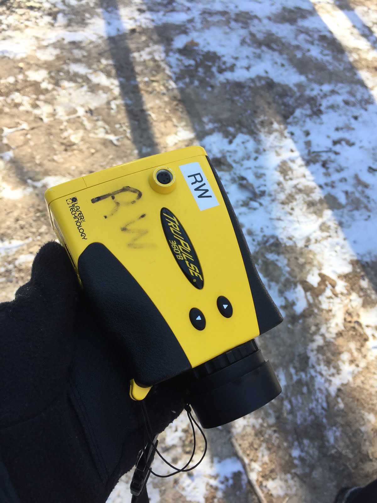
Figure 5. Laser distance finder used at location 1 to find distance and azimuth.
Location 2:
Location 2 used the least advanced technology of the three surveying techniques used. A tape measure, Figure 6 was used to measure the distance of the surveyed tree from the origin. The benefit of this technique is that it is extremely low tech and there is no worry that the device will run out of battery or have technological issues because it does not operate on batteries. This type of surveying should be used in extreme climates that would drain battery life quickly.
At this location first the coordinates of the origin were recorded using the GPS device. Next at the origin the azimuth of the targeted tree was taken by using the compass. Next the tape measure was used by having someone at the origin hold one end of the tape measure and having someone else walk the other end to the surveyed tree to get the distance from the origin to where the tree was. Lastly the DBH tape was used to measure the diameter at breast height of each surveyed tree. All four of these measurements were recorded. Problems encountered where that only trees in the direct line of sight of the origin with no interference from other things in the park could be measured. The tape measure needed to be able to directly stretch from the origin to the surveyed tree, it could not bend to move around a different object, otherwise the measurement would not be accurate. Another problem was in making sure the tape measure was tight when measuring. The farther away the tree was from the origin the more likely the measuring tape was to sag. Another problem was that the surveyor had to physically move to the object being surveyed to get the distance, if a river had to be crossed or a mud pit, this method would not be realistic to use. To avoid these problems location 2 was surveyed in an area of the park that was more open and had a 360 degree span of trees. Also the location had terrain that was easy to walk on and trees short distances from the origin.

Figure 6. Tape Measure used at location 2 to find distance.
Location 3:
At location 3 a distance finder device was used. The device had two parts, one held at the origin and one held to the tree. The part held at the origin would need to be pointed to the part held against the tree and once a button on the origin part was pressed the tree part would beep. The distance in meters measured between the two devices would display on the screen of the origin held part. The benefit of this survey method is that it is physically targeting another physical component of the device leading to consistency and accuracy. This device could be used to survey the distance of a wide variety of objects or locations. The limitation of the application of this method is that the one component has to physically be moved to the surveyed object so this method could not be used in hazardous locations.
At this location first the coordinates of the origin were recorded using the GPS device. Next at the origin the azimuth of the targeted tree was taken by using the compass. Next the distance finder device was used to get the distance from the origin to the tree. Lastly the DBH tape was used to measure the diameter at breast height of each surveyed tree. All four of these measurements were recorded in a notebook. Problems encountered where that if there was a large object, like a large tree, separating the two parts of the distance finder device the distance could not be registered. Also like with the tape measure the surveyor had to physically move to the object being surveyed to get the distance, if a river had to be crossed or a mud pit, this method would not be realistic to use, but unlike the tape measure, there was no physical component between the two ends so if there was a river that could be crossed by bridge the distance could be recorded across. To avoid these problems the origin was placed in an open area that did not have trees blocking other trees.

Figure 7.
Following the survey, the four measurements for each of the three locations were manually entered and organized in an excel spreadsheet, Figure 8. At each location ten trees were surveyed resulting in a survey of 30 trees.

Figure 8. Each of the four measurements: coordinates, distance, azimuth, and tree diameter, for each tree surveyed in an excel spreadsheet.
After the data was organized and inputted into excel the excel spreadsheet was imported into a new file geodatabase. The table was brought into ArcMap and the points were assessed to check that the data appeared correct. Next two tools were run on the data points. First, the Data Management tool: Bearing Distance to Line tool was used, by entering the excel table as the input table, setting the x field to the Longitude field, the y field to the Latitude field, the distance field to the distance column, and the bearing field to the azimuth field. This tool creates a new feature class containing line features after taking into account the x and y coordinated, distance, and azimuth of coordinate locations. The second tool run was the Data Management Tool: Feature Vertices to Points tool. The input was the output that came from the Bearing Distance to Line tool. This tool creates a new feature class containing points from the vertices from the line features created in the Bearing Distance to Line tool. In Figure 9, the output from both tools after being used in ArcMap is shown.

Figure 9.
Results
The results of plotting the location of surveyed trees worked really well. Every surveyed tree was appropriately represented in the results. The only concerns regarding the results of the study was that Putnam Park is a very hilly area with many different elevations. With all 3 surveying methods there is some concern that elevation changes might have skewed the distance result. This data could be used implicit geographic data. As for the diameter measurements of the trees, it is expected that those should be fairly accurate with the only concern being that the DBH would vary by the surveyor's breast height which could skew the measurements. Another concern is that the software made the origin points symbolized as a tree. They are not trees by rather origin points from where the data was measured. Overall the data appears accurate and a reliable data source. Figures 10 and 11 show the results from the survey.

Figure 10. Locations 1, 2, and 3 are located in order left to right in the image.
The surveyed locations of the 30 trees surveyed.
Figure

Figure 11. The 30 trees surveyed in putnam park symolized
according to their DBH measurements.
SourcesWisconsin department of Natural Resources. (n.d.). Retrieved March 27, 2017, from http://dnr.wi.gov/topic/Lands/naturalareas/index.asp?SNA=134.